Modern transmissions increasingly require bearings that operate at higher speeds.
For example, in electric vehicle (EV) transmissions, the higher speeds are a result of a drive for improved efficiency.
Firstly, how do we define when a bearing is operating at “high-speed”?
This doesn’t just depend on the bearing speed, but also on the size of the bearing.
Usually “high-speed” means that the bearing dn value is greater than 1,000,000.
dn = Diameter in mm x Speed in RPM
Immediately we can see that reducing the size of the bearing can negate the impact of higher speeds, but then the ability of the bearing to carry load will be reduced, so compromises must be made.
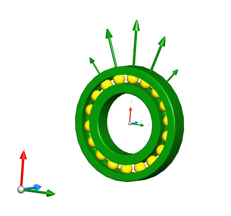
A bearing under radial load. The force arrows show the forces on the elements.
Secondly, when a bearing is operating at high-speed, what exactly are the problems that this causes?
Although the centrifugal force on the elements and the cage will increase, this isn’t directly a problem.
Usually the main considerations are overheating, cage failure, and smearing.
Heat is generated at the element-raceway contacts because due to the bearing geometry and deflections, the ball or roller will be sliding in certain regions of the contact instead of rolling.
Ball bearings have a smaller contact area than roller bearings such as CRBs, which means less friction and hence less heat generation, so are often preferred to roller bearings at high speed.
Ceramic elements are lighter and stiffer than steel ones, with the increased elastic modulus reducing the size of the contact area (and hence heat generated) even further, but this will be at the cost of increasing pressure on the raceway.
Whichever type of bearing is used, if it is not cooled adequately then this can eventually lead to collapse of the fluid film between the element and the raceway, leading to even further heating, and hence damage.
This article will focus on the behaviour of ball bearings at high speed, but much of it is also relevant to roller bearings.
Smearing
Smearing is another phenomenon caused by the contact between the element and raceway and is most likely to occur as an element moves from an unloaded region to a loaded region of the bearing.
As this transition occurs, the ball’s angular velocity is changed rapidly as the friction increases between the ball and raceways.
When the power loss per unit area in a contact patch exceeds a certain amount, the surface of the raceway is at risk of experiencing smearing damage.
Cage Failure
Cage failure at high speeds is usually a result of fatigue from repeated impacts between the balls and the cage, and sometimes the cage and inner/outer ring.
If a bearing is not loaded equally at all points, the elements will orbit at different speeds.
This will result in the elements orbiting faster than the cage in some regions, and orbiting slower in others, which will lead to ball-cage impacts.
The magnitude of the impact forces and thus the risk of cage failure, will depend of the cage design, cage material and loading conditions.
How Can We Predict When These Effects Are Likely To Cause A Problem?
Ideally, we would like to anticipate such problems before manufacturing anything, hence the use of analytic and numerical methods as part of the design process.
Traditionally, quasi-static analytic models of ball bearings used two degrees of freedom, the two displacements of the ball in the radial plane through the ball centre.
It is then necessary to make further assumptions about the ball’s angular velocity in order to calculate sliding speeds at the contact patches.
Often this has been done by assuming that either the inner or the outer raceway (depending on bearing speed) is “controlling”, and hence will balance the gyroscopic moment on the ball.
For lower speeds or where only the stiffness of the bearing is required these assumptions work well.
At higher speeds the error in the sliding speeds can generate significant errors in the calculation of the frictional forces.
Quasi-static Ball Bearing Model For High-speed Situations
Released in MASTA 12, SMT developed its own quasi-static ball bearing model for high-speed situations, with six degrees of freedom included.
As well as the two ball displacements in the plane, this new model also treats the ball orbit speed and rotational vector as variables.
The model is solved by finding the combination of displacements and speeds that give zero force and moment residual around the ball coordinate system axes.
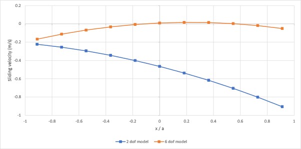
By solving for these additional speeds, it is possible to have a much more accurate description of the sliding speed distribution at the ball-raceway contacts.
Comparison between sliding velocities along the semi-major axis of the contact patch using the two degree-of-freedom model and the new six degree-of-freedom model.
Accuracy Of The Calculation of All The Forces On The Ball
Integral to this new model is the accuracy of the calculation of all the forces on the ball.
One of the most important is how to calculate frictional forces on the ball from the contact patch.
A simple approach would be to assume that the total coefficient of friction is constant, which is equivalent to Coulomb friction, and approximates dry contact.
For oil-lubricated contacts this model will give inaccurate results, especially at lower speeds where an oil lubricated contact will behave qualitatively differently.
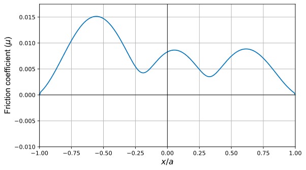
MASTA has an advanced lubricant model for fully lubricated contacts, considering asperity effects, lubricant rheology, temperature, and pressure.
This model can operate in multiple lubrication regimes such as iso-viscous rigid (IVR) and piezo-viscous elastic (PVE, commonly known as EHD/EHL), with the lubrication regime being considered depending on the entrainment speed and pressure at the contact.
An example lubricant model friction coefficient along the semi-major axis of the contact patch.
Hydrodynamic Rolling Force
Another important force to consider is the hydrodynamic rolling force, often neglected in ball bearing models, or misattributed to drag.
Due to the pressure gradient in the contact area, there is an additional braking force on the ball.
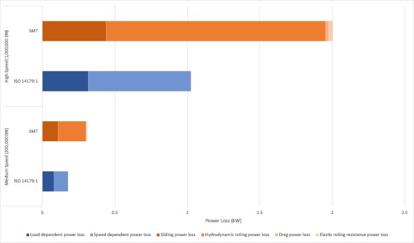
The extra detail in this new model allows for the accurate prediction of each component of power loss, and hence heat generation in ball bearings.
Furthermore, it can produce metrics that indicate how likely smearing is going to occur.
Traditionally gearbox designers would use international standards such as ISO 14179 to estimate power losses, but with this new model it is possible to investigate different bearing geometry, oil rheology, temperatures, loads (including per-element load) or other operating conditions, which goes way beyond the ability of these standards.
Power losses from an example bearing running at high and medium speeds. ISO 14179 splits power loss into speed-dependant and load-dependant components, whilst the new model provides power loss information in greater detail.
Dynamic Bearing Models
Dynamic bearing models provide the ability to model the cage and its interaction with the element and guiding ring.
Fortunately, the model developed here can be easily adapted to perform dynamic analysis.
This model will use all the detailed forces and the advanced friction model detailed for the quasi-static case here and will be discussed in more detail in a later article.
Thank You For Reading
Further details about the models underpinning the new high-speed ball bearing analysis can be found in two papers recently published by SMT in Tribology Transactions.
Tribological Models for Advanced Ball Bearing Simulation
Bearing Models for Advanced Ball Bearing Simulation
We also recently wrote a blog on ‘Sidebands In Gear Noise Due To Manufacturing Errors‘ which may be of interest.
Related Blogs
Sidebands In Gear Noise Due To Manufacturing Errors
Discover how the automotive industry uses a high-fidelity MASTA analysis for NVH in electric vehicle drivetrains. This article explores the interplay of manufacturing errors, gear whine, and resulting noise.

