Spline rumble is characterised by a multiple low shaft order droning noise.
It arises in electrified vehicle (EV) powertrains due to excitation at the spline connection between the motor rotor and the transmission input. It is caused by the interactions between manufacturing errors.
In this article we will be looking at how SMT’s MASTA can be used to predict rumble in a modern EV gearbox with a three bearing input assembly layout.
We’ll use a quasi-static analysis in MASTA Advanced System Deflection to understand the fundamental mechanism and predict the excitation force at the spline.
Then we’ll use a time stepping analysis using MASTA’s DRIVA modules to fully model the non-linear dynamics.
Finally, we’ll perform a sensitivity study on the manufacturing errors to see how different errors contribute to rumble.
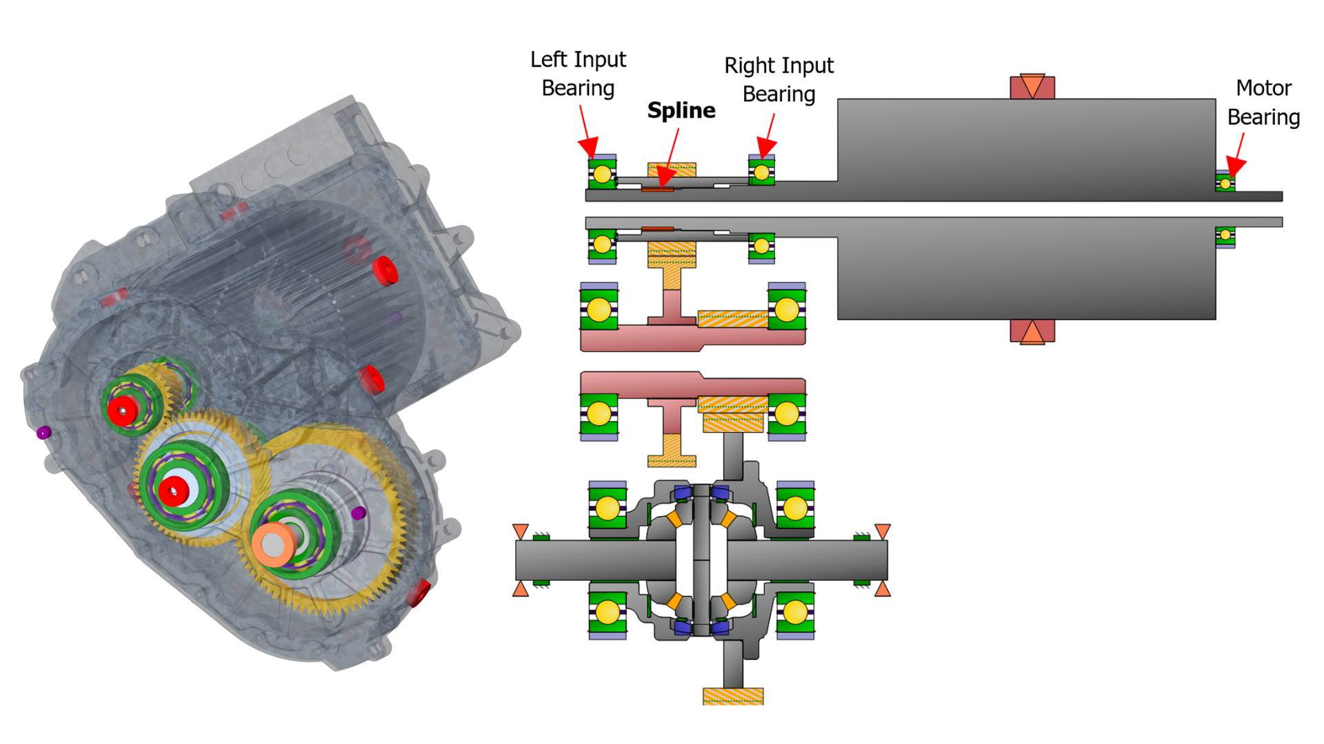
EV Powertrain with three bearing input assembly (rotor + transmission input shaft) layout.
Spline Rumble Mechanism
Spline rumble is caused by the interaction between rotating and static loads, on the spline, exciting shaft bending modes.
These loads come from manufacturing errors such as spline pitch errors and bearing radial offset errors.
Spline pitch errors can affect tooth thickness and/or spacing. This will cause a variation in contact between each tooth pair as the errors will cause some teeth to start contacting and bending before others.
This means there is a resultant radial force which rotates synchronously with the shafts.
Radial misalignment between bearings will introduce a static load on the spline.
This misalignment could occur if bearings are located in different components of the housing assembly, where misalignment of housing components themselves will misalign the bearings.
While these loads are of the first rotating order of the shaft, the interaction between these loads causes a response of multiple low orders.
This is what we call spline rumble.
In order to predict spline rumble in MASTA, two functionalities will be used:
- Advanced System Deflection (ASD): For quasi-static steady state analysis. This module allows for a quick approximation of the excitation force generated at the spline but won’t be able to model the non-linear dynamics of rumble. This module is most effective in early design phases for quick prototyping of potential layouts. It also helps with visualising and understanding the mechanism behind rumble which will be done later in this article.
- DRIVA: Full 6DOF time domain multi-body dynamics. A time domain analysis is necessary to accurately model the non-linear stiffness effects involved in spline rumble, including response through resonance. Due to longer runtimes as the analysis is far more complex, this module is best suited for later design phases to provide confidence in your final designs.
Input Assembly Bearing Layout
The powertrain chosen for this study has a three bearing layout for its input assembly. The rotor shaft extends under the transmission input shaft where a side fit spline connects the two shafts together.
There are a few advantages of this layout particularly over four bearing arrangements.
It is lower cost and is more compact.
A downside could be maintenance of the more compact design.
Advanced System Deflection For Steady State Rumble Analysis
The powertrain has some manufacturing errors that we are able to predict the impact of.
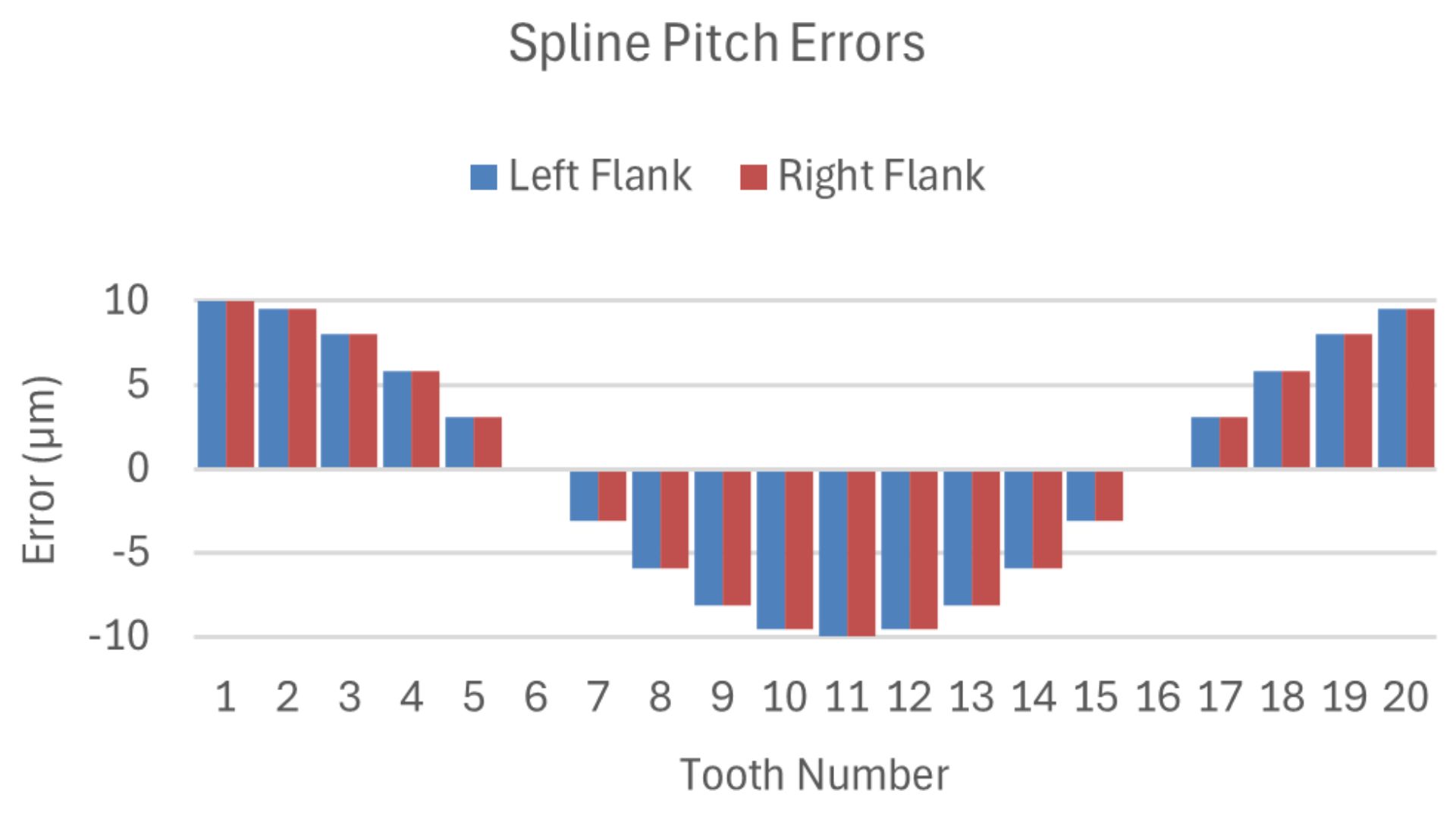
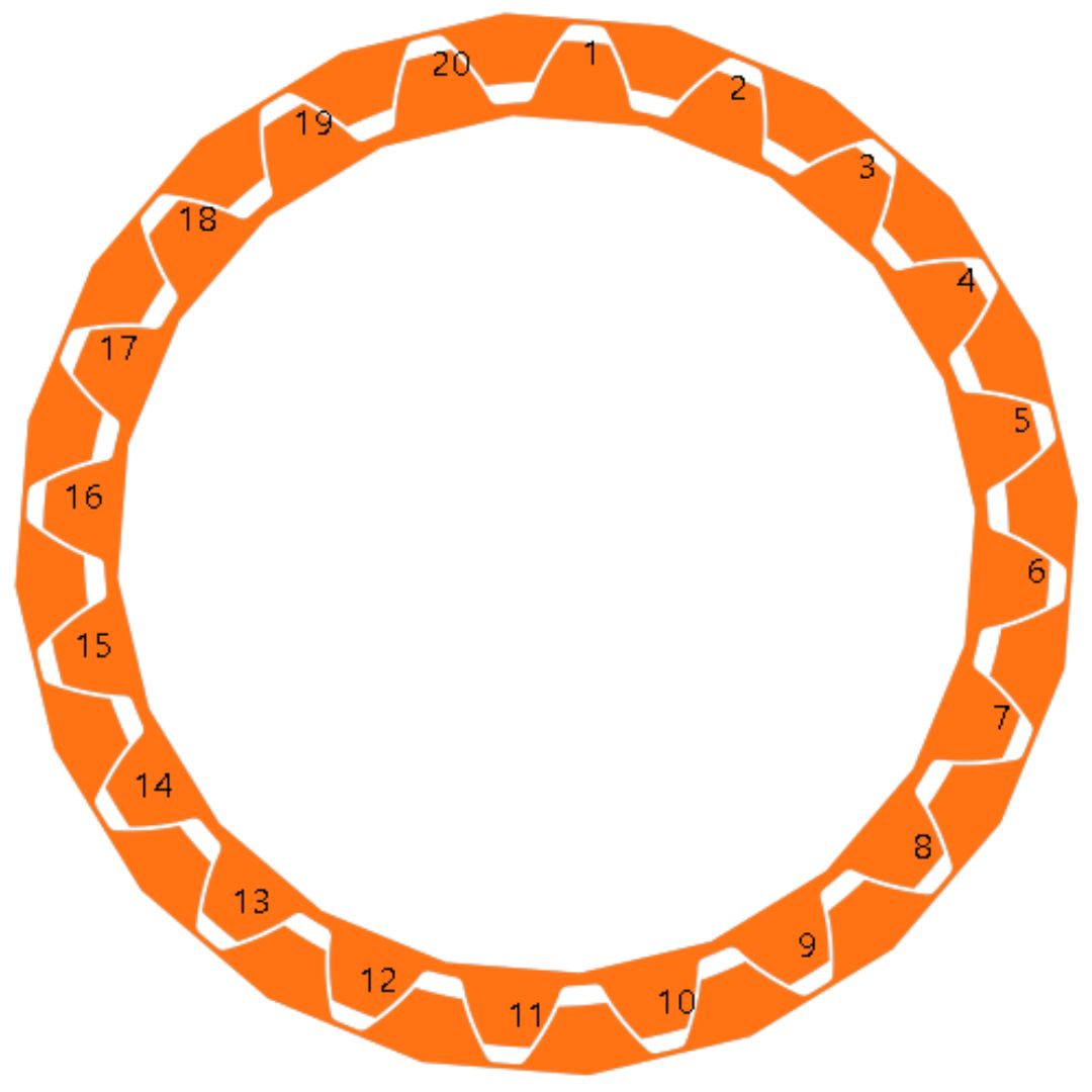
In this study, the spline is modelled with sinusoidal pitch errors with a peak to peak amplitude of 20μm, and the right input and motor bearings have radial offset errors of 100μm.
Spline Pitch Errors.
We’ll start by using ASD to understand the fundamental rumble mechanism and predict the excitation force generated at the spline:
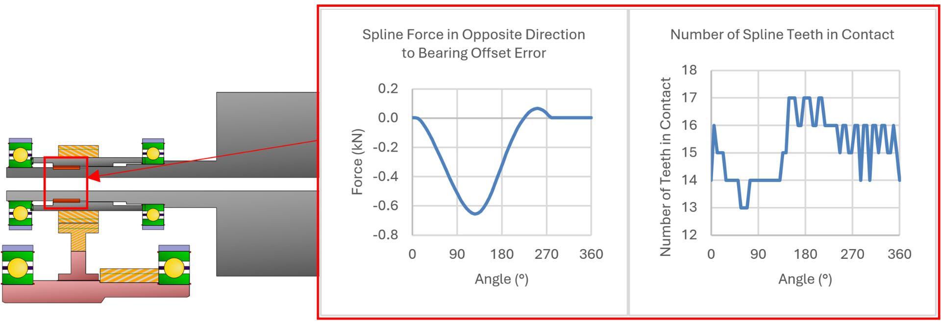
Spline force and contact status from ASD.
Spline contact and loading at different angles. Tooth with max pitch error denoted by the red triangle. Bearing offset in vertical direction.
![]() Red triangle = tooth with max pitch error.
Red triangle = tooth with max pitch error.
Animation of spline tooth contact variation during rotation.
Looking at the spline behaviour over a single rotation, the variation in spline teeth contacts and loads can be seen, both of which are determined by the two manufacturing errors.
The spline load reaches its maximum when the force on the tooth with the highest pitch error (Red Triangle) is in the opposite direction to the bearing offset error.
The number of spline teeth in contact is at its minimum at this point. Conversely, the impact of the two errors counteract each other for part of the rotation, resulting in negligible resultant force.
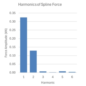
Looking at the same result in the frequency domain reveals that the spline force has multiple orders characteristic of rumble:
Harmonics of Spline Force ASD.
ASD is most useful during early design phases for assessing potential layouts by comparing the excitation force at the spline.
This helps narrow down options to carry forward for time domain analysis.
Changing the layout could improve spline rumble, but this could impact gear whine noise.
Designs carried forward for time domain analysis would therefore have low spline force harmonics in MASTA ASD but also low response at the housing and its mounts due to gear whine calculated in MASTA NVH.
DRIVA For Dynamic Rumble Analysis
The quasi-static analysis using ASD assists with understanding the mechanism behind spline rumble and predicts the excitation force generated at the spline, but it’s critical to understand the dynamic response particularly when passing through resonances.
Because this will be a highly non-linear problem, a full time domain solution is required which is undertaken using MASTA’s DRIVA modules.
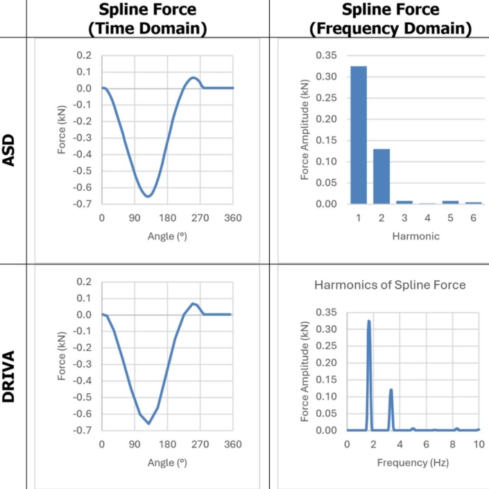
Before looking at the response at higher speed, DRIVA can be compared to ASD at low speed as a validation check, as a quasi-static solution and a low speed time domain solution should be equivalent.
We’ll compare against the spline force ASD result we obtained in the previous section.
The results are very similar:
DRIVA vs ASD for spline force at low speed.
Up until now, we’ve only considered results at the root cause of rumble being the spline.
However, as with most NVH problems, best test data correlation is achieved when comparing response nearer to the casing.
Therefore, we’ll look at the dynamic force of the bearings on the casing.
An effective way to capture the dynamics across a range of speeds in a time domain analysis is to perform a run-up.
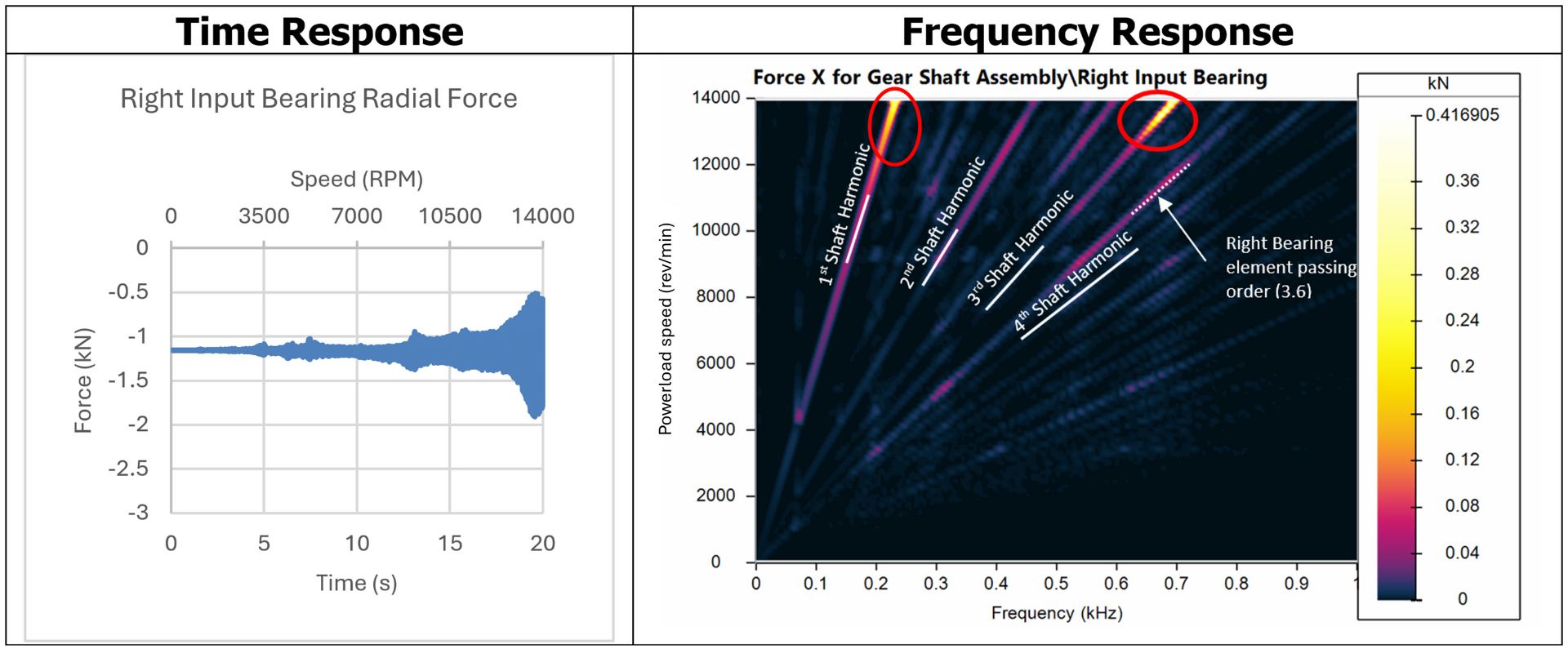
Below is the time and frequency domain results for the right input bearing force, during a run-up over the full motor speed range:
Right bearing radial force response during run-up.
Conclusions that can be made regarding the rumble behaviour:
- The response has multiple low orders with high response which is characteristic of spline rumble.
- There are two prominent resonances for the first and third harmonic. These have been circled in the waterfall plot. Both these resonances occur near top speed.
- In addition to the integer shaft harmonics, there are many additional orders. Some will be due to the bearing element passing orders, e.g. one has been highlighted on the figure.
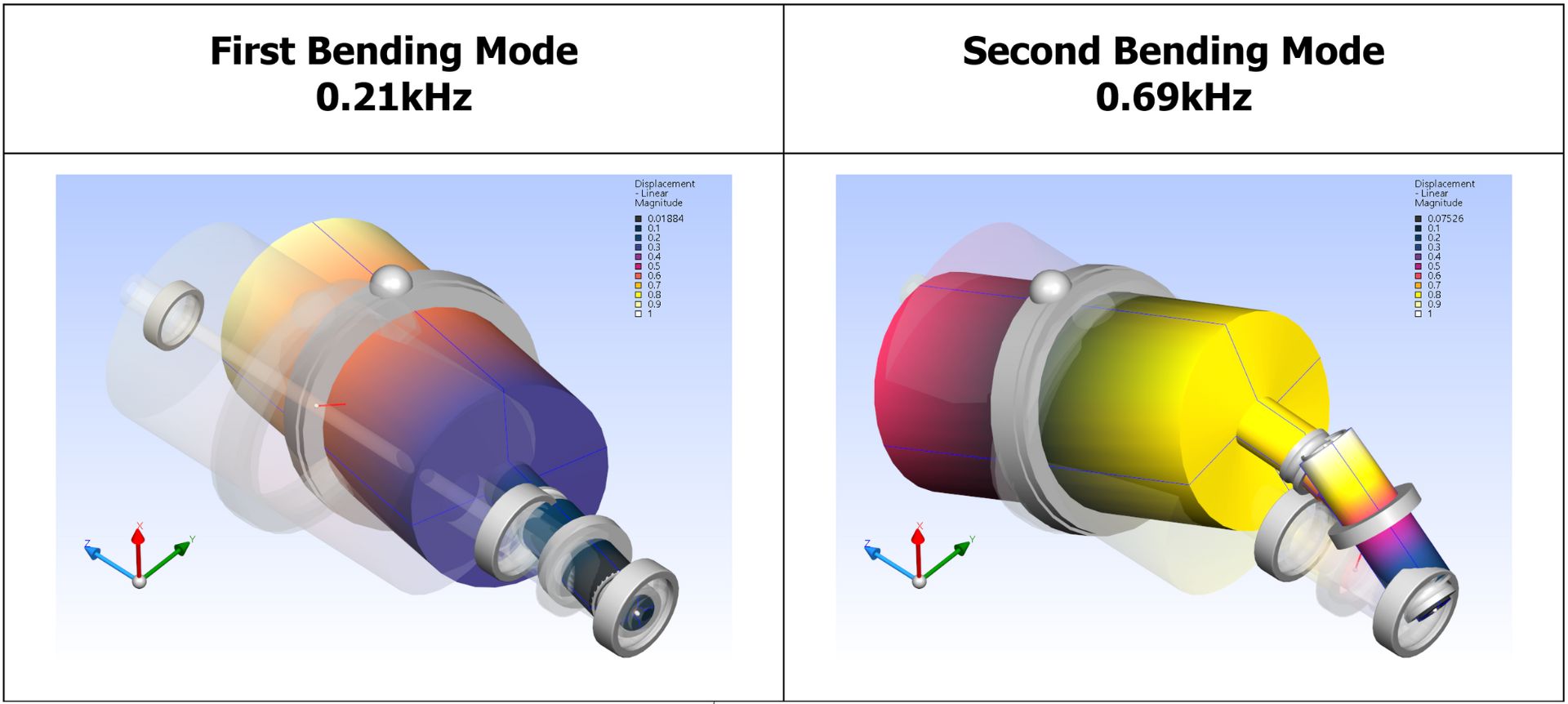
The two identified resonances are excitations of the first two bending modes of the rotor and gearbox input shaft assembly that are shown below:
Input assembly bearing modes excited by spline rumble.
We have now understood the dynamic response of the system across its entire speed range and identified unwanted resonances caused by spline rumble exciting bending modes.
Manufacturing Error Study
This section will explore the impact of each manufacturing error on the rumble response by varying the amount of each error one at a time.
We’ll start with the impact of bearing offset error, where the spline pitch error is kept at 20μm peak-to-peak amplitude.
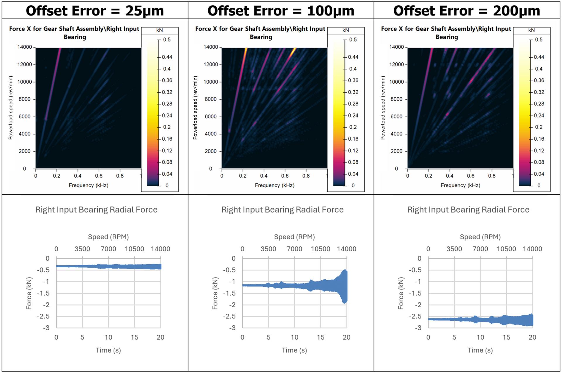
The below DRIVA results show how the bearing offset error affects the right bearing force:
Impact of bearing offset error on right input bearing force.
It’s expected that increasing offset error will increase the load on the bearings.
This can be seen in the DRIVA results, where the average load on the right input bearing increases with the error.
In addition to this, the offset error affects the system modal model.
The large resonance of the third harmonic due to excitation of the second bending mode near top speed with 100μm of error does not appear at much lower or higher error.
This is because the offset error also affects the bearing element loading, which affects the bearing stiffness, which affects the second bending mode frequency to the extent that it can be moved out or into the operating range.
Next, we’ll look at the impact of pitch error by varying it whilst fixing the bearing offset error to 100μm.
It was found that changing the error had more of an effect on the left bearing than the right bearing, so we’ll look at results for the left bearing.
Because the pitch errors have been applied as a sinusoid, a higher pitch error will result in a greater variation in tooth thickness around the spline.
This means the load sharing between the teeth will be more concentrated near the thicker teeth. This leads to a greater resultant radial force, and therefore more severe rumble.
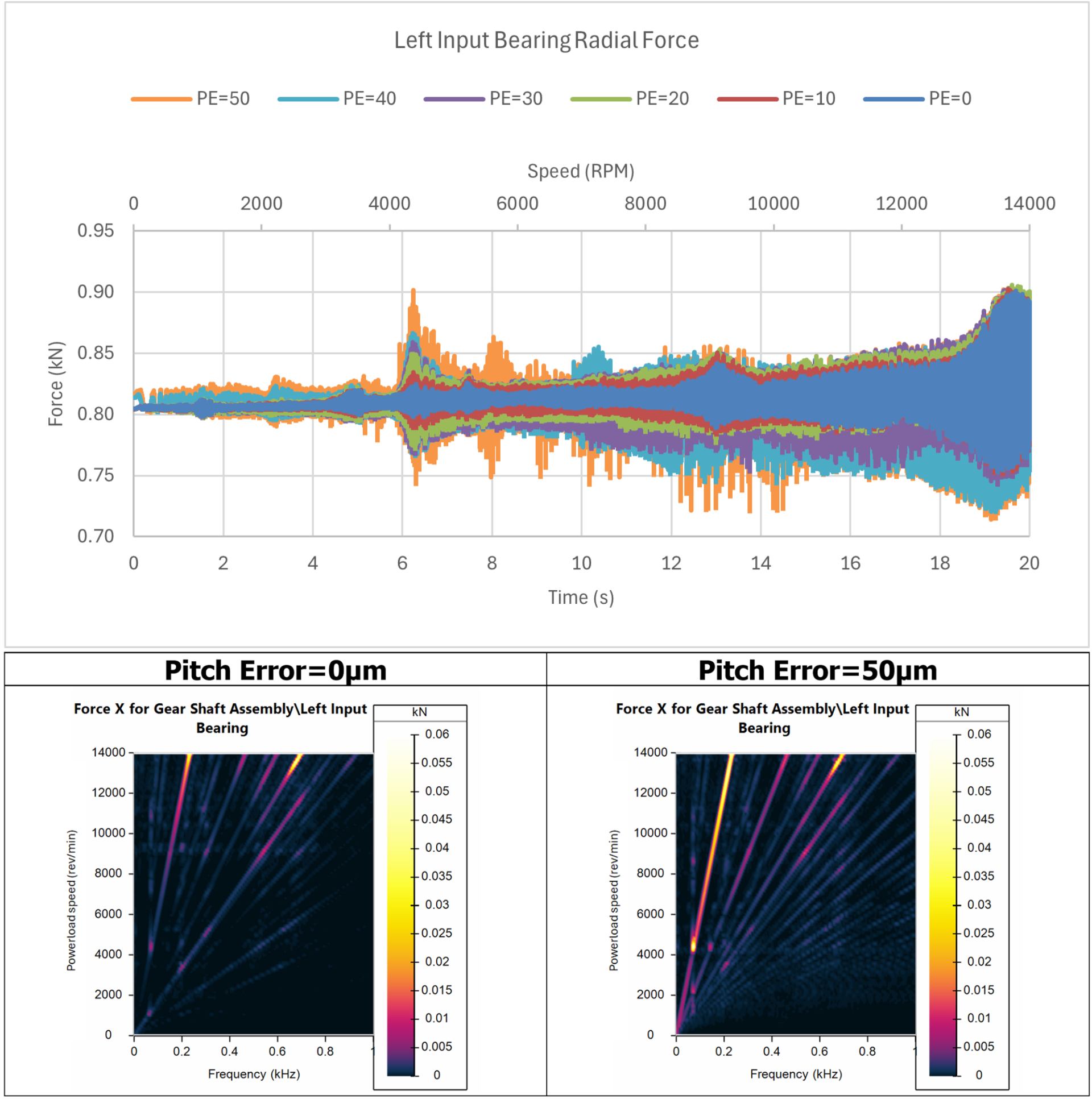
These predictions align with the DRIVA results as shown below:
Impact of bearing offset error on left input bearing force.
As expected, the bearing force amplitude increases with pitch error.
Pitch error appears to influence most orders, but particularly the first order.
This makes sense as the sinusoidal pitch errors will generate a once per revolution rotating force that will increase the first order directly, but also increase higher orders because of how the pitch errors interact with other errors.
Thank You For Reading
In summary, we have covered how DRIVA and ASD can be used to predict spline rumble noise.
MASTA ASD gives a quicker quasi-static solution for early design phases and for understanding the fundamental mechanism.
DRIVA’s full time domain solution by comparison offers a comprehensive prediction of the system dynamics.
Using DRIVA, we have understood the impact of two different manufacturing errors that can interact to cause rumble.
Related Blogs
High-Speed Ball Bearings – Challenges and Analysis
This article explores and focusses on the behaviour of ball bearings at high speed, but much of it is also relevant to roller bearings.
ABOUT THE AUTHOR
Simon Terry
Simon Terry has been a Research Engineer at SMT since September 2019.
With a Masters (MEng) in Mechanical Engineering from the University of Nottingham, Simon’s specialist areas are Automotive NVH and Dynamics.
Most recently, Simon has been focusing on applications of MASTA’s time-stepping module: DRIVA for gear rattle.
In his free time, Simon enjoys hiking around the countryside and national parks.

