Modern assembly lines rely on robotic arms for efficient and precise manufacturing. In some applications, they are required to carry heavy loads whilst maintaining this high accuracy.
In this article, you’ll see how bearing parameters in a robotics transmission were optimised to improve the drive’s performance characteristics whilst maintaining component lifetimes.
MASTA’s Cycloidal drive functionality was used to model the system and MASTA’s static analysis tool, System Deflection, was used to gather the static results required for optimisation.
The key performance characteristic focused on is the drive’s moment stiffness and the main optimisation strategy used the axial preload of angular contact ball and taper roller bearings to increase their radial stiffness.
This was to decrease deflection when a payload is held by the arm.
We also investigated the impact of applying negative radial internal clearance on the eccentric bearing for reducing cycloidal pin contact stress.
While these preloading and clearance parameters helped to improve the reducer’s performance, they also acted to reduce bearing lives. A compromise was thus required.
Moment Stiffness in Robotics
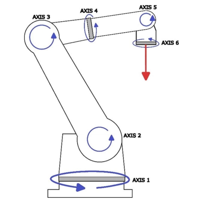
Figure 1: Basic 6 Axis Robot Arm
In robotic arm applications, significant moment loads can be applied to certain axes of the system when the arm is holding a payload.
Each axis has a reducer used for speed reduction from a driving motor to allow for slow speed, high torque arm rotation. The applied moment loads are supported by the bearings within this reducer.
As these robots need high positional accuracy, deflection under load should be minimised to meet requirements.
In a 6-axis robot, the 4th axis reducer experiences high moment loads due to its position in the arm. As such, maximising the moment stiffness of this 4th joint and thus the reducer and bearings within them is of key importance.
The Model
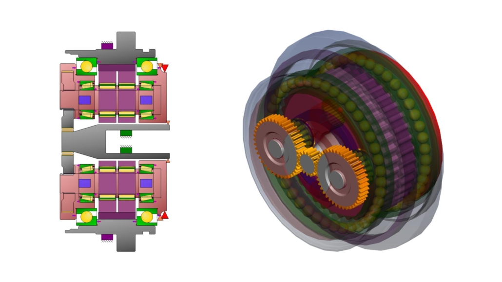
Figure 2: a) 2D Model of Reducer b) 3D Model of Reducer
Figure 2 shows an example design based on publicly available specifications of a commercial cycloidal drive with planetary input, which is used in the 4th axis of robot arms with a maximum 50kg payload.
This was modelled as having a 30 kg baseline payload for the arm weight and tools, and a total payload including carried item of 50 kg.
To capture this within the MASTA model, we applied a point load with an equivalent force and moment to holding the payload at 1m from the end of the arm.
Further, the duty cycle used consisted of four steady state load cases totalling a 100,000-hour life to represent repetitive pick and place actions of the arm, which are summarised below in Table 1:
| Load Case | Payload (kg) | Torque (Nm) | Time (hrs) |
| 1 | 30 | 0 | 25,000 |
| 2 | 30 | 200 | 25,000 |
| 3 | 50 | 0 | 25,000 |
| 4 | 50 | 200 | 25,000 |
Table 1: Duty Cycle
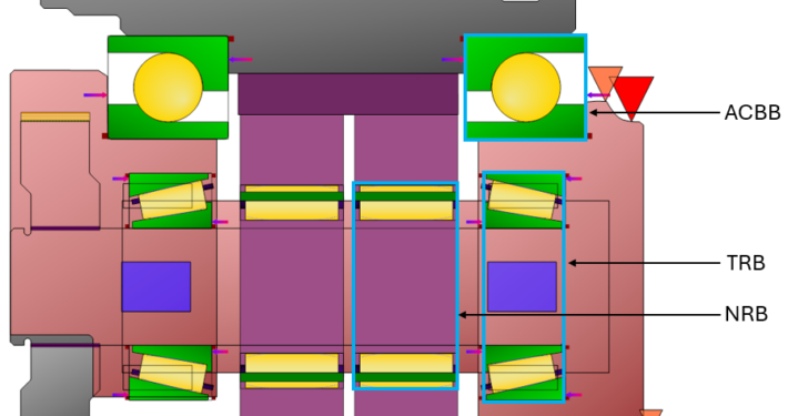
Figure 3: Bearings of the System
There are three types of bearings in the system (Figure 3), the angular contact ball bearing (ACBBs), taper roller bearings (TRBs) and needle roller bearings (NRBs).
The ACBBs are there to take external loads, such as the moment load. The TRBs take load due to misalignment of the planet pins, and the NRBs take the eccentric load from the discs.
Optimising For Moment Stiffness
Figure 4: Bearing Preload on ACBB
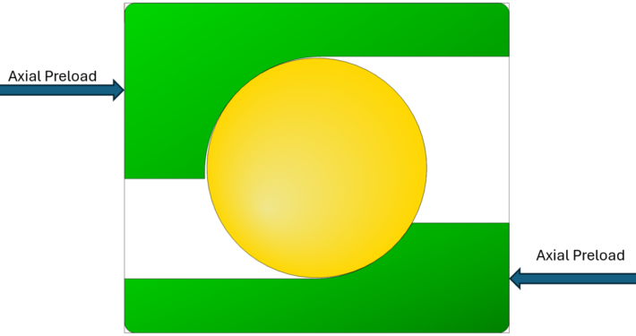
The approach used for this optimisation was the introduction of axial preload (Figure 4) to both the ACBBs and TRBs using the axial displacement method. Equal preload was applied to bearings of the same type for simplicity.
The addition of axial preload caused an increase in moment stiffness of these angular bearings due to pre-stress effects.
However, this also caused an increase in bearing stress and decreases bearing life. Thus, bearing life was considered as a limiting factor when using this method to maximise moment stiffness.
Due to a lack of information about lubricating conditions, ISO 16281 Basic Reference Rating Life was used to predict the life of each of the bearings. If lubrication conditions are known ISO 16281 Modified Reference Rating Life should instead be used.
Further, due to the variation in misalignment of the planet pins that will occur with varying stiffness, we also aimed to optimise for transmission accuracy of the reducer.
In this analysis, a parametric study of the axial displacement preload of the ACBBs was varied between 0 µm and 70 µm whilst the TRBs’ varied between 0 µm and 32.5 µm. This applied a preload force from 0 kN to 60 kN on the ACBBs and from 0 kN to 1.1 kN on the TRBs.
For this study, MASTA’s Parametric Study Tool (PST) was used for a full factorial study. This allowed to us to understand and visualise the full design space of the problem and optimise manually. A more sophisticated procedure could use an automatic optimiser.
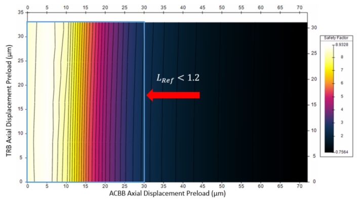
Firstly, we identified the constraints on our optimisation by looking at the bearing lives. The life of the right ACBB against both axial displacement preloads (Figure 5) showed that it depends only on its own axial preload, and decreases with it.
Requiring a reasonable safety factor of 1.2 or above, we chose a maximum displacement preload of 30 µm (17.9 kN).
Figure 5: Right ACBB Life Safety Factor against ADPs
Note: The left ACBB’s safety factor has similar dependence to the right ACBB’s whilst taking larger values, thus the predefined constraint is sufficient.
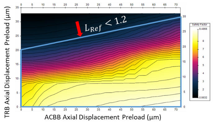
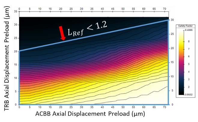
Examining the lives of the TRBs (Figure 6), we saw that they vary with the axial preload of both ACBBs and TRBs.
We found that below the line plotted on both graphs the life of both TRBs is above 1.2, the required factor.
Figure 6: a) Left TRB Life Safety Factor Against ADPs b) Right TRB Life Safety Factor Against ADPs
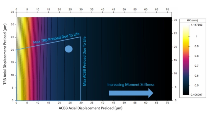
Finally, we looked at both the angular displacement of the arm (Figure 7) and System TE (Figure 8), only allowing values in our allowed range due to life constraints.
We saw that the angular displacement decreases with increasing ACBBs preloaded, which is as expected from the increasing stiffness.
Figure 7: Angular Deflection of Arm Against ADPs
System TE was slightly more complex, as there is a minimum with the ACBBs at 10 µm displacement preload (3.6 kN) and the TRBs’ displacement preload at 32.5 µm (1.1 kN).
Generally, an increasing TRB axial preload and an ACBB displacement preload close to 10 µm (3.6 kN) was ideal for transmission accuracy.
Figure 8: System Transmission Error Against ADPs
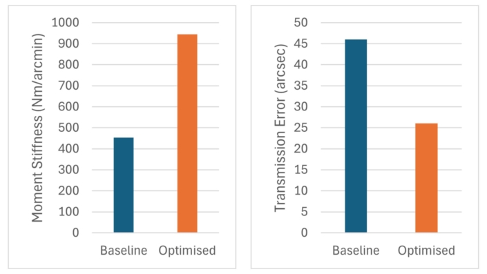
A good compromise was struck by picking 25 µm (13.7 kN) ACBB Preload and 20 µm (0.54 kN) TRB Preload, which gave a significant improvement over the baseline model without preload, shown in Figure 9.
Figure 9: Baseline vs Optimised a) Moment Stiffness b) Transmission Error
Optimising Eccentric Bearing Radial Internal Clearance
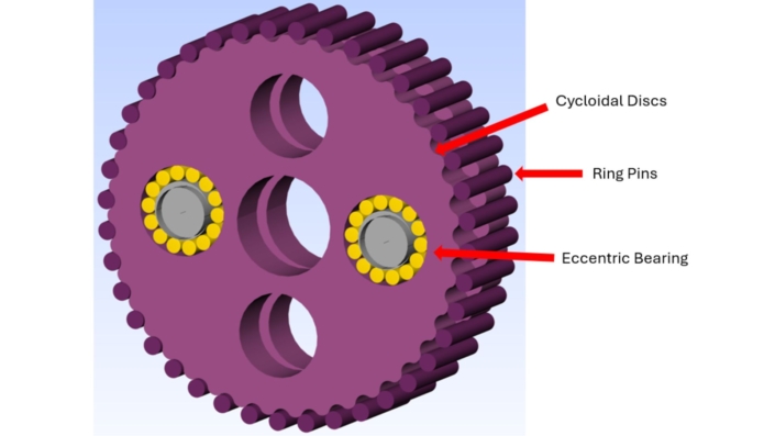
Figure 10: Cycloidal Assembly
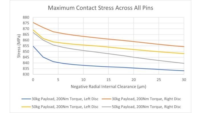
Another study was also conducted to look at how the application of a negative Radial Internal Clearance (RIC) to the eccentric bearing affects its own life and the maximum contact stiffness across the ring pins (Figure 10). The study varied between 0 um and -30 um of RIC.
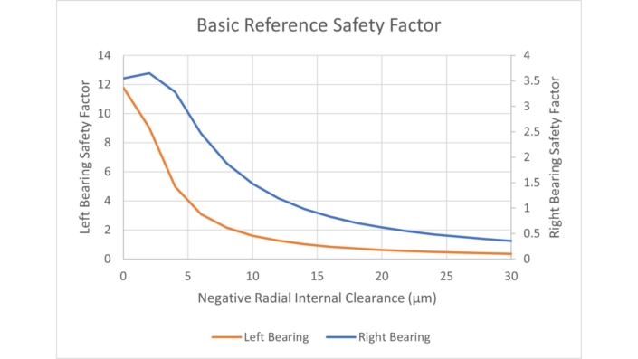
We saw that increasing the magnitude of negative RIC causes significant decrease in the life of the needle roller bearing and slightly decreases the maximum contact stress on the cycloidal drive pins in all load cases.
Figure 11: NRB Life Against Negative RIC
Figure 12: Maximum Pin Contact Stress Against Negative RIC
To reduce the maximum pin contact stress and keep the bearing life still significantly above limiting values, we picked a -5 µm RIC.
The baseline value was 907 MPa, which reduced to 875 MPa with the introduction of axial preloads and finally to 866 MPa when negative RIC was introduced.
Thank You For Reading
In this blog, we have shown how MASTA can be used to optimise the moment stiffness of a cycloidal drive in an industrial robotics application, whilst still accounting for other constraints such as bearing life and transmission accuracy.
This was done using a combination of axial displacement preloads on the angular contact ball and taper roller bearings.
We have also explored how cycloidal pin contact stress can be reduced by increasing magnitude of negative radial internal clearance of the eccentric bearing.
Related Blogs
High-Speed Ball Bearings – Challenges and Analysis
This article explores and focusses on the behaviour of ball bearings at high speed, but much of it is also relevant to roller bearings.
High-Speed Ball Bearings – Dynamic Models
We look at the dynamic modelling of ball bearings, and the benefits of this approach when analysing high-speed ball bearings.

