In this article, we’ll be exploring why unloaded gear rattle occurs and how it relates to engine torsional vibrations.
Then, we’ll look at how MASTA’s DRIVA modules can be used to capture the non-linear tooth separation effects needed to accurately model rattle in a vehicle on road scenario.
What Is Unloaded Gear Rattle?
Unloaded gear rattle is a common noise problem in multi-speed transmissions. It is characterised as repeated separations and impacts of gear teeth in gearsets whose synchroniser is disengaged.
This results in an unpleasant broadband noise. It’s therefore important to be able to predict rattle using CAE software, so that it can be mitigated through informed design changes.
With engine down-speeding trends for improved fuel economy, torsional vibrations in the engine have also increased.
This has increased the likelihood of rattle, and therefore increased the requirement for more advanced gearbox vibration isolation methods such as dual mass flywheels.
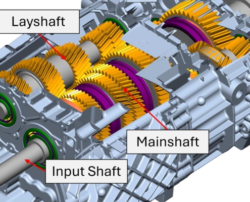
Figure 1 – Twin Layshaft Truck Gearbox.
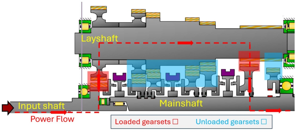
Figure 2 – Loaded and Unloaded Gears.
Unloaded Gear Rattle Mechanism
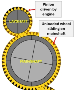
The severity of rattle in a gearset is determined by the balance of inertial forces at the driving pinion and the drag forces at the unloaded wheel:
Figure 3 – Unloaded Gearset.
The inertial force is calculated from the speed fluctuations of the driving pinion.
Internal combustion engines generate torsional oscillations due to intermittent piston firing.
These oscillations can be transmitted to the gearbox and therefore cause the speed fluctuations.
The drag force comes from friction and lubrication effects.
This should consider factors such as the friction forces due to the sliding of the unloaded wheel on its shaft, gear churning and meshing losses, and losses due to fluid shearing between disconnected synchroniser halves.
If the inertial force exceeds the drag force, gear separation and therefore rattle will occur.
The severity of the rattle will generally be worse the greater the inertial and drag force difference is.
As gear rattle requires modelling of tooth contact separation, a non-linear mesh stiffness model is required.
This can be done through a time stepping multi-body dynamic analysis, achievable with MASTA’s DRIVA modules.
Modelling Unloaded Gear Rattle In A Heavy Truck
We’ll now see how a full heavy truck powertrain from engine to wheels can be modelled.
As the engine’s vibration will vary with speed, a run-up analysis in DRIVA will be performed to evaluate gear rattle severity for a broad range of operating conditions.
While DRIVA is capable of modelling synchroniser shifting, the run-up will be performed entirely in 5th gear in wide open throttle for simplicity.
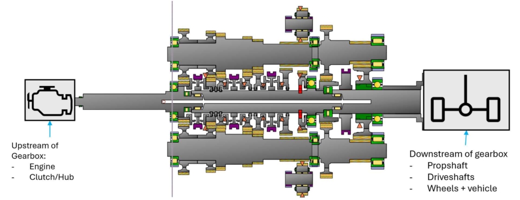
Figure 4 – Heavy Truck Powertrain in MASTA.
In order to accurately capture gear rattle, we will utilise a high-fidelity 6DOF gearbox model.
Since we only need to capture their effects on the gearbox, the upstream/downstream components can be modelled though simpler 1D torsional models.
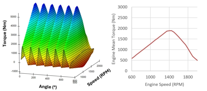
To provide the necessary inertial forces on the driving pinion to observe gear rattle, the engine is modelled with a speed and crankshaft angle dependent torque.
The engine is based on a 6-cylinder engine with a main firing order of 3:
Figure 5 – Engine Torque as a Function of Speed and Crankshaft Angle.
As the engine speed increases, both the engine torque, and torque amplitude increases up until around 1400RPM. Beyond this speed, the torque decreases as the time window for each ignition cycle becomes too short for optimal performance.
The engine is connected to the gearbox via a clutch flywheel mechanism that aims to isolate engine torsional vibrations from the gearbox.
Beyond modelling the gearbox and engine, we have made a number of additional considerations to model realistic engine/drag torques thus simulating real-world driving conditions.
As well as 1D models of the propshaft, differential and driveshafts, the gearbox downstream assembly also considers vehicle properties such as tyre-to-road friction, speed dependant vehicle air resistance and vehicle inertia.
This all means that a realistic engine torque is driving the detailed gearbox model, that has an output drag torque representative of real world conditions.
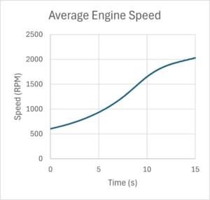
The resulting average engine speed is given below:
Figure 6 – Average Engine Speed Over Time During Run-Up.
DRIVA Results Analysis
Now that the powertrain model and loading conditions have been established, rattle can be predicted for a range of flywheel designs with varying engine vibration isolation performance.
The metric used to judge rattle severity in MASTA is impact power, which is calculated from the tooth contact force multiplied by the gear pair relative velocity.
Compared to just looking at the contact status, this result distinguishes between louder and quieter impacts.
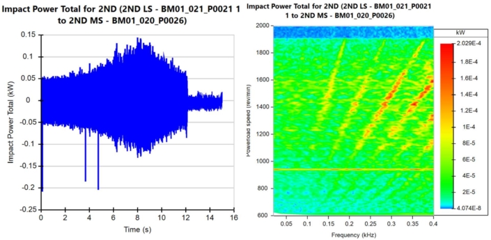
To start with, we’ll look at the rattle severity of the 2nd gearset with a single mass flywheel which provides poor engine vibration isolation:
Figure 7 – Single Mass Flywheel Rattle Severity.
With this flywheel, rattle is present for the entire run-up.
The severity of rattle however does vary with speed with the most severe rattle occurring at around 8-9s or near 1400RPM.
This is expected as this is the speed where the engine torque oscillations are at their highest, meaning that the inertial force on the pinion is at its highest.
You can see several clear orders in the waterfall plot, which are the harmonics of the main engine firing order.
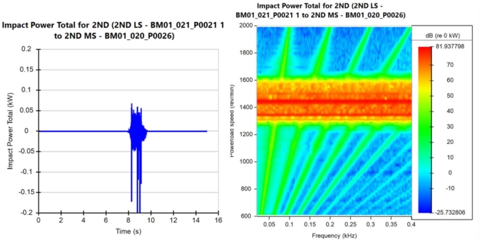
Next, we can swap the single mass flywheel for a sub-optimally tuned dual mass flywheel.
This design partially removes the rattle but doesn’t mitigate it at peak torque.
This is visualised in the waterfall plot, where the characteristic rattle broadband noise is only present at peak torque or near 1400RPM.
A dB scale has been used here to show both the very high response broadband rattle and the very low response engine orders:
Figure 8 – Sub-Optimal Dual Mass Flywheel Rattle Severity.
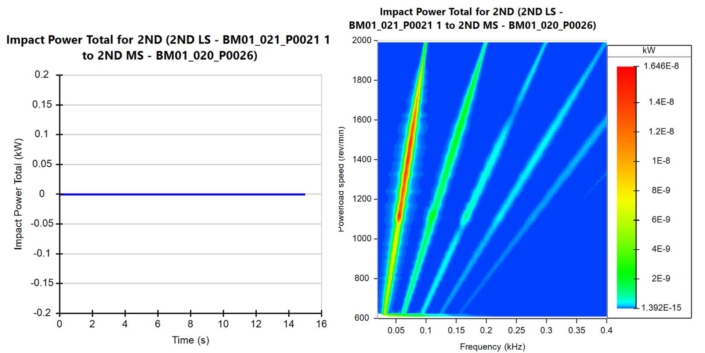
Finally, an optimal dual mass flywheel design eliminates rattle completely:
Figure 9 – Rattle Mitigation With Dual Mass Flywheel.
Conclusion
In this article we’ve seen how MASTA’s DRIVA modules can be used for unloaded gear rattle prediction in full powertrain models.
This involves combining a detailed heavy truck gearbox model with 1D up/downstream models for realistic engine and vehicle loads on the gearbox.
The rattle severity could then be determined for different flywheel designs to demonstrate the relationship between rattle severity and engine vibration isolation performance.
Related Blogs
Predicting Spline Rumble
This article explores how to predict rumble in a modern EV gearbox using MASTA, covering quasi-static analysis, a time stepping analysis and manufacturing errors to see how different errors contribute to rumble.

