Plunge Shaving Dynamics
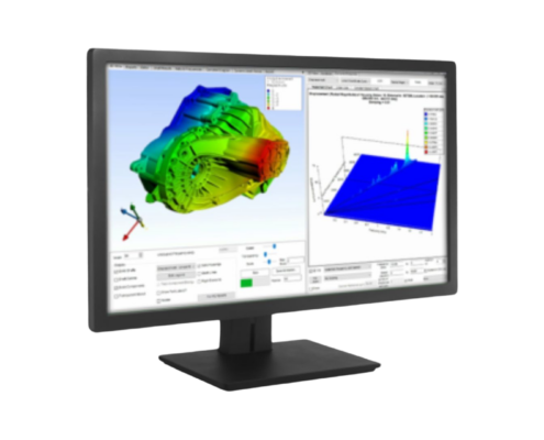
A new module that enables simulation of the shaving force variation from the gear tip to root according to the shaving method, which determines whether the tooth profile will have additional profile/lead error
Hobbing Process Simulation
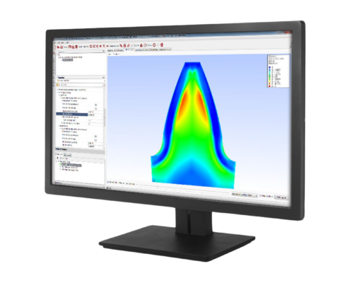
This newly revised and updated module considers the variety of static errors in the machining process for gear hobbing. The process simulation module can reproduce the gear geometry, including deviations, under the manufacturing conditions
Enhanced Mesh Coefficient of Friction Options For Power Loss/Efficiency Calculation
New Coefficient of Friction calculation methods are now available in addition to the previously available ISO/TR 14179-1:2001 method
Gear Flank Loading INDICATOR
Indication of which are the loaded gear flanks. In Powerflow mode you can visualise flank loading in both 2D and 3D Views. In other modes the option is available in 2D View
Inclusion of The Effect of Shot Peening On ISO Calculated Gear Bending Stresses
For ISO gear materials specify that a material is shot peened and then specify a Shot Peening Bending Stress Benefit percentage for inclusion in the gear rating
Gear Tolerance Standards
- When performing cylindrical gear rating to AGMA 2101-D04 it is now possible to specify to use the AGMA 2000-A88 and ANSI/AGMA ISO 1328-1-B14 Tolerance Standards in addition to the existing AGMA 2015-1-A01 standard
- When performing cylindrical gear rating to ISO 6336 it is now possible to specify to use the ISO 1328-1:2013(E)/ISO 1328-2:1997(E) Tolerance Standard in addition to the existing ISO 1328-1:1995(E)/ISO 1328-2:1997(E) standard
- It is possible to select the Tolerance Rounding System to be Metric or Imperial
Bevel/Hypoid Gear Misalignments
Include a table of misalignments calculated with respect to the gear mesh point in addition to the previous results that are calculated with respect to the cross point
Improved CAD Reports
- CAD reports have been enhanced from previous releases and now include the ability to add more data and information in CAD Gear Data Sheets
- Include images with property labels where values are updated to reflect the design/analysis values.
- Specify the CAD report template
Roller Bearing Improvements
Include user-specified X, Y factors for Dynamic Equivalent Load calculation for cylindrical roller bearings which can take axial load in addition to estimated factors.
LDP Import
Bring in basic design from LDP. This initial implementation is limited to internal or external cylindrical gear pairs and only macro geometry is currently imported.
FE Component Node Connection Report
Three new tables are included in the default report for an imported FE component in Design mode that show the expected and actual locations of the FE nodes on the connected component as an aid to assess the accuracy of the imported FE
Bearing Node Alignment With Imported FE
Specify whether FE condensation nodes for the bearings have been created at the centre of the bearing or at the centre of the bearing race. This is especially useful for bearings such as taper roller bearings where the race of the bearing is not always the full width of the bearing
Cylindrical Gear Misalignment Calculation Methods
Cylindrical gear misalignment calculations based on alternative misalignment definitions
AGMA Rating Using LTCA Calculated Values
Use LTCA Stresses when performing gear rating according to AGMA 2101-D04 in Micro Geometry mode by selecting the option at the bottom of the AGMA rating options in the Cylindrical Gear Rating section of the Settings
Welding/Structural Factor
A new option to specify the Welding/Structural Factor, Xw, as used in scuffing calculations

